UPDATE:
I’ve put out ePub (Safari users, right-click to download, otherwise it tries to load the ePub in Safari), edited version of this post. Things are tidied up and organized to be a little easier.
The always interesting Dr. Drang posted this rather entertaining bestiary of construction equipment to help the masses. It spurred me on to, jokingly, create a glossary of visual effects terms that almost no normal human being would ever need to know.
In 3D programs, the origin is (0,0,0) in world space. The position of almost everything is in some way related to this origin (or to the camera, but more on that later.) Even in a 2D compositing package, operations need to understand where two images may overlap, and the compositing package will use (0,0) to figure that out. Where different packages choose to put 0, and which axis is which, varies between software vendors.
In 3D software packages, this is your window to manipulating objects in the world in 3D space. It’s not accurate for lighting, shading, or texturing under default conditions, because it is designed to be fast and interactive.
The act of producing a raster image from either a 2D or 3D set of assets.
Rendering every frame of a batch of frames, one after the other, on a single machine.
A bunch of a computers that are networked together and accept ‘jobs’ commands to render a frame, or set of frames, and return the result to disk. This is so no one has to batch render frames that take minutes, or often hours, to produce.
Renders of each frame receive a unique file name when written to disk, with the frame number included in the name of the file. To make sure these files look pretty, the number is padded. for example:
awesome_animation.1.exr
awesome_animation.56.exr
Lame.
awesome_animation.0001.exr
awesome_animation.0056.exr
This is pretty obvious, this is everything as it relates to your scene’s origin. That is your ‘world’ in the file.
Everything relative to the camera in the scene. The camera is an infinitely small point, but it has an orientation, a field of view, and a position in space relative to the world origin. Things in camera space move in directions relative to the camera, not to the scene origin directly.
Expanding the view of the camera to include areas outside of the field of view. This data can be useful for seeing things just off screen in the viewer, or later on, when rendering it can provide additional pixels for use in certain compositing operations that might shrink the frame slightly.
Every computer model of a camera has a near, and a far, clipping plane. The plane is measured from the camera. This can be used as an optimization, to ignore everything off in the distance that is not required, or to ignore particles that are 0.001 units from the camera and would produce crappy results.
Just like in your geometry class, a vertex is a point. Infinitely small, but given a specific location in world, or camera space. With a collection of points, connections can be made. With 2 points, you have an edge. With 3 points you have 3 edges, and 1 face, making a triangle. With 4 points, you have 4 edges, and 1 face, making a square. Any higher number of faces is termed an n-gon. Verticies can store information other than their position.
Two, joined vertices produce an edge. This would be a ‘line’ in your geometry class.
Three, or more, edges are required to make a face. This is drawing a triangle, or a square, on a piece of paper, and then filling it in. This is useful for making surfaces to look at, or for calculating simulated collisions, and many other things.
Different software packages will include different primitives, but they typically consist of spheres, cones, cubes, etc. Some software vendors will include more complicated geometric constructs under their ‘primitives’ menu — fun things like teapots, and ponies.
The verb for making geometry. A particular artist might specialize in modeling. They are not voguing at work, they just make things in computers that may or may not be animated to vogue.
Non Uniform Reticulating Bezier Splines. They are fancy, vector based splines that allow for curvy edges, instead of a direct-line linking two points like a polygon mesh. The wikipedia page for them is pretty dang neat.
This is a point in space that dictates the vector stuff for your curve.
Two control points, with tangents and stuff. Think of curves in 2D vector graphics programs like Adobe Illustrator. A curve can also be shaded to have width in world space, or relative to camera, which is how most CG hair is made.
One big square. Every complicated object is made with this one sheet of imaginary voodoo. Each sheet can be subdivided in to really tiny pieces through a process called tessellation. A NURBS Sphere is just the sheet wrapped in space with inifitely small top and bottom points. You wind up with a seam down one side of the sphere. A NURBS Cube is 6 NURBS Surfaces with all their edges meeting. More complicated shapes can be made by using booleans to cut holes in the surface (but the surface is still ‘there’ in a sense, just stenciled out of existence, so it’s a little weird). Another technique is to stitch patches of NURBS planes together to make a character, but if the seams weren’t perfect, they’d pop, just like an improperly sewn garment.
NURBS were very popular in the 90s because they allowed for very smooth surfaces to be made without having a very dense polygon count. It fell out of fashion and mostly subdivision surfaces are used.
This is like a polygon surface, but the surface can be divided in to smaller and smaller faces, and then reverted back to a base mesh. This makes it easy to work with a lightweight version of your character in your scene, and then only subdividing it for renders where the extra detail is required.
The joined, polygonal, or subdivision surface.
Depending on the specifics of a software packaged, a piece of geometry can be loaded, once, and instanced to many locations in the world. Trees, buildings, leaves, crowd animation, anything. There are usually systems to manage these instances in ways that can randomize them, or pick from a library of different sources based on certain conditions. Instancing is really good for memory optimization, since you can potentially load only a few things, but render thousands of versions of them.
An edge loop is basically following an edge all the way around a polygonal mesh until it loops back on itself. draw a line around your knuckle, perpendicular to your finger, and you will have an edge loop around your knuckle. These kinds of surface features are important when you move on to deforming geometry because it can create areas that compress and expand without tearing, or crinkling.
The wikipedia explanation is kind of a pain to read. A normal is basically a vector calculated from a surface. The vector of an edge, or a face, can be changed to simulate the look of a crease, or a completely smooth, round surface. Video games rely heavily on manipulating surface normals to make low-poly surfaces look smooth, or more detailed, but often betray the illusion along the silhouette of the object, or character. Under optimal circumstances, this can be used with texture maps to bend the light on the surface inside of each face. This can give the illusion of detail that would require an enormous amount of geometry. The way that a surface normal is calculated usually means that it’s best to use polygons with only three, or four, sides.
This is the default position, and properties, of your geometry before you’ve applied rigging to it. It is your muppet without the hand in inside, all perched and ready to go. A good bind pose is important because it dictates what everything looks like before you start stretching and compressing surfaces, and thus stretching and compressing any textures on those surfaces. In most cases, a human being will be standing with their arms sticking out at an angle from their torso. Arms straight to the side, or arms straight ahead, will have very severe stretching in almost any situation that is not to the side, or ahead. Having them at an angle gives you a nice middle ground, and a more natural look. Bind pose could be anything though, pugs, caterpillars, chairs, etc. It’s just whatever the most natural default is.
X, Y, and Z are already used, so who ya gonna call? UVs! Ahem. UVs are the 2D vectors along a plane used to texture objects (and other fun stuff that requires 2D surface coordinates). Because your object is in 3D space, and the textures are in 2D space, you have to either project 2D space on to your object, or unwrap your object to a 2D plane.
You can project UVs on to a surface mesh from your camera, from an orthographic view of the top, or the side. You can project them in a cylinder. If you have anything more complicated that a tin can, or a sphere, then you’re going to need to unwrap your surface. Imagine you have an action figure in your hand, and it’s just a thin shell, no thickness at all. Now imagine cutting in to the action figure so you can unfold it on to a piece of paper. You’ll need to bend your model in some places, which means your UV coordinates on your mesh will not be exactly lined up with where the XYZ coordinates are. This is neccesary, but moving these points too far apart means that you’re going to have something that will look stretched, or compressed, when the 2D surface is is painted and reapplied to your model. You can cut it in to a bunch of individual faces, but then you will have texture seams EVERYWHERE. Good luck matching the painted edges of each of those! Sucker!
Per-face Texture Mapping (That would really be PFTEX, let’s be real) is a technique of skipping UV layout. This means you will need to paint in 3D space or you will have seams. This is better explained in this video that has a big head, and little arms.
The invisible armature in your model that controls it. This is made of things that look like, and are referred to as, bones. They are comprised of joints.
The act of making a fake skeleton.
The person that makes the fake skeleton.
Like a vertex, but for your rig. It’s position, and rotation, will influence the mesh it is bound to. Joints are parented to one another to create ‘bones’ and when the top-level joint is rotated, or translated, all the underlying joints move with it.
You take your invisible skeleton, and your geometry, and you tell the software that the skeleton should drive that geometry.
Whenever you manipulate the points of a mesh, you are modeling, because you’ve produced a frozen object. It is what it is. When you add the element of time, it becomes deformation. If you have a lump of clay, it is a model. If you push your finger in to, it will smush as you push it, over time. You’ve deformed it. Now imagine you could do that with a computer. N-gons will deform in really funky, and unpredictable way, because the surface within the edges will recalculate as some verticies get closer, and farther away, from one another. N-gons suck. This is also why an edge loop will create the illusion of something bending smoothly, as all the parallel edges curl along a perpendicular, deforming one. Quads are really superior here, in almost every application.
These are imaginary points, like vertices, or joints, that can be parented in weird places. They can affect the surface like a joint, with weighted influence, but they often are used as the building blocks for more complicated deformers.
Tools in a software package that can manipulate surfaces, or points, in very specific — often single-purpose — ways. For example, you might have a ripple deformer, which will make a ripple through the surface, as if it was the surface of a pond and you dropped a stone in it. Many packages have deformers that function almost like mini-rigs, all prepped for you to use where you see fit, for that specific task.
Not like weight lifting. This is just a term for the amount of influence a deformer, or a joint, can have on the mesh that is effecting. If you had a joint in your human character’s upper arm, and one in their elbow, you’d want to control the amount of influence each joint exerted on the surface. When your elbow bends, it should not be moving the top of your shoulder down. Typically, weights are adjusted by ‘painting’ them with a tool in your software package. Some joints might be added along a bone, in places that are not anatomical joints in a human body, just for the purposes of weighting the mesh with more fine-tuned control.
Constraints are invisible rules that govern how different objects relate to one another inside the 3D scene. Usually they keep things ‘together’.
Glueing something to a point in space. Rotation, and scale are unaffected.
This makes something line up with the rotation values of something else in world space.
This is like parenting two objects, but it doesn’t change the hierarchy of the scene, since it uses the constraint to do it.
When you curl your finger, that’s FK. The base joint moves, the next knuckle moves, and so on. The movement is inherited according to how joints are parented. Fingers, and arms are obvious for FK.
This is when you push off of something. When a human walks, their feet stay planted on the ground until they are lifted off the surface. If this was FK, then the hip, knee, and ankle would all move and move the foot, it wouldn’t stay planted on the ground. Almost any rig is littered with FK/IK switches to go between which system works best.
You take a mesh, duplicated it, and deform it. Then you tell the software package which one is the source, and which one is the target. Now you’ll have a blendshape value that can be adjusted to linearly translate the points from their original location to the new location. It’s mighty-morphing technology. Because the movement is linear, inbetween shapes are often modeled. This can be for things like sculpted muscles, or lips.
NURBS curves that float in space around your rig. They are typically parented to specific parts of the mesh, or the joints of the rig, so that the controls move through space with the character. The curves are used as proxies for manipulating the armature. Directly manipulating the joints is something only an insane novice would think to do. Control curves give you the ability to set functional properties that can be reversed, animated, or connected to other properties through expressions, or constraints.
This is the fun part that most people think is super neat. This is where you take your character and you make it do things by assigning mathematical values that change over time. (I’m kidding, your mostly dragging those curves around, math sucks, bro.)
Frames are a unit of time. A certain number of frames results in a certain number of seconds. Everyone’s seen nerdy sites that freak out about FPS (First Person Shooters (No, I’m kidding, I mean Frames Per Second)). Most film is played back at 24 frames per second.
A frame where a value is explicitly set. With several of these frames, and values that change over time, you create animation because crap will move around from one place to the other. Wikipedia has handy graphics for this one, including one blue scribble that might give you a seizure.
The implicit behavior that occurs between two keyframes. If you keyframe a ball in one corner of a room, and then you keyframe the ball in the opposite corner of the room, the ball will linearly translate from one position to the next. You did not give it any keyframes in the middle. You can change this interpolation in every animation package with a curve editor. This is a graph of that plots the value of your keyframed attribute in Y, and the frame number in X. You can change that linear interpolation to a smooth curve, that will make the ball appear to slowly accelerate, move quickly in the middle of the room, and slowly decelerate. You didn’t add any keys for that, it’s all handled by the tangents of that curve.
A style of animation where all the essential keyframes are created, resulting in the character, or object, moving from one ‘pose’ immediately to the next. The inbetween frames are often refined later, but a certain ‘snappy’ quality often remains.
Stepping through, one frame at a time, and setting a keyframe on every frame. This used to be more common in certain 2D animation styles. It is still used when specifically tracking to a 2D, recorded performance.
Max Fleischer originated it (suck it, Walt!) but some of the most memorable rotoscoped scenes are from Disney films, such as Snow White and the Seven Dwarfs (shoot). The technique requires tracing every frame recorded footage. These days it is most commonly used to describe matte generation (tracing photography with splines in a 2D compositing application). It can be applied in 3D, with a CG character’s performance being viewed from a camera, and matched to a live-action performance. This is different from motion capture, because the performance is only photographically recorded, and no 3D data for the performance is generated. Animators typically look down on this for the same reason that artists look down on tracing portraits from photos.
Just what it sounds like, a cycle of animation of a character walking. These cycles can be added to libraries and reused when needed where animating every footstep a background character might take would be tedious.
A first pass of animation where interpolation is usually disabled. This leads to just a rough overview, like an old-style animatic.
You take a bunch of storyboards, time them out, and you get a very, very, very rough animation of your movie. Temp recordings of dialog, and sometimes temp music, are added to the animatic. This can help the director see what he wants to do. It is almost exclusively used in completely animated productions these days, though it has been used for live-action movies that have animated characters.
This is basically doing a rough job at the modeling, texturing, and animation, to make a not-pretty mock-up of what the visual effects, or CG characters will look like later. It’s like an animatic, but WAY more expensive. Previz is essential during some live-action shoots because it allows the director to direct his actors so they will more easily integrate with the final work done at a later time. Pretty much nothing is kept from previz except for whatever is used in editorial. This editorial cut will be used by animators to make their animation, like a very expensive animatic.
Again, I defer to Wikipedia on this one.
Because everything is computer perfect, and all the poses were set on nice, clean keyframes, there’s going to be twinning. When two things happen at the same time.
Some of the keys are dragged around to happen before, or after the keyframe they were originally set on. This provides overlapping action. Instead of a character raising both arms at the same time, one will move a frame or so before the other. This produces a fluid, natural range of movement without twinning.
Once all the keyframes are set, the animation is typically offset to prevent twinning. Pixar did this with their eye blinks too. If you pause a Pixar movie when a character is blinking you will see that the eyes are closing and opening on different frames.
You’ve got your Pixar-level, super-duper, awesome animation all set, but it’s typically good form to actually watch it before you tell anyone it’s good. You do this by telling your animation software to basically capture a screenshot of the view in your application for every frame, and then stitch that back together in to a movie. Certain bells and whistles will vary from application to application, but this is an essential step to evaluate animation, because almost nothing will play back in realtime inside of the viewer of your application. This is a kind of batch render.
It is very important on a live action film project to track the camera movement, and camera properties, of the real-world camera so that everything be constructed in a way that works for whatever else you plan on doing. The photographic plate needs to be unwarped (the bowing effect from the camera lens removed so you have a flat image) and different algorithmic solvers can give you a good head start on figuring out the space.
This mostly includes texturing, but not the actual work of laying out UVs. It is primarily concerned with the application of shaders, with specifically-set material properties to your geometry.
This is a view of just the edges that make up a surface. This was commonly used in the 1980s and 1990s in graphical overlays to show how high-tech something was. It’s most useful in an interactive viewer. There are also special wireframe shaders that let you render something with backface culling and adjustable thickness to the wireframe edges.
Even in the basic preview the application’s viewer presents to you, things are shaded (often in OpenGL). Since vertices are infinitely small, something has to draw a dot there for you to visualize. Surfaces are shaded with some default material that usually resembles plastic. A shader is the code snippet that tells whatever is rendering the view how to return the pixels. When light hits a surface, at a certain vector, it will trigger some component of the code to shade the surface in a specific way.
Materials are often referred to separately from shaders. A shader is a chunk of code, and materials are basically a group of preset values to use with that shader. This distinction is often confusing, and most people think of shaders and materials as being the same thing.
Let there be light! The diffuse lookup is the matte illumination of the surface. Think of a mostly matte surface like concrete. It illuminates pretty evenly when light hits it.
Shiny! The bright, hot highlights on a surface are specular components. This is typically a very tight lookup of the relationship between the light, the surface normal, and the camera.
Shiny? Technically, reflection is specular, and specular is reflection. Many software packages split the two, which allows for easy adjustment of one or the other. Reflection can be most easily thought of as chrome, but even human skin and concrete reflects the world around it.
Bendy! A surface normal controls how light hits a surface, but refraction controls how light transmits through a surface. Glass, water, prisms, your grandmother’s ugly candy dish, are all refractive objects. The angle the light travels through the object bends based on the index of refraction, which is a measurable property of any real world substance.
Google around for some tables. They’re fun. The Index of Refraction is the measurement of blah blah blah. Even gold has a refractive index. Light doesn’t pass through gold, you say? Well there’s a direct relationship between reflectivity and the Index of Refraction. Physically accurate shading models will even tie these values together so that RoI can drive refraction, reflection, and fresnel.
The term refers to the rolloff exponent in a shader, but it can be tied to a physically accurate model that uses the Index of Refraction to drive the fresnel. Nonsensical fresnel effects can be used to achieve certain non-photorealistic looks, like “X-Ray” shaders, or shaders that cheat the look of hand drawn cel animation edges.
Bending surface normals with mapped, or procedurally-generated data. This allows for the illusion of internal detail on model surfaces, but the edges will still look like flat geometry edges. Bump maps are typically within a set range, and black and white. with one being up, and the other being down. This varies depending on the package. Special kinds of maps can use RGB vectors to provide more detail than the straight up and down of bumps.
This is like a bump value in a shader, but it actually deforms the surface of the mesh. If your mesh lacks sufficient polygons, you’re going to get a pretty crappy displacement. Because displacement requires a certain density of the mesh, it can be extremely computationally time consuming. The displacement must also occur to the mesh before many other actions are taken by the renderer. Some neat effects can be achieved with animated displacement, where a sequence of images might represent footprints in snow, or the surface of an ocean. Vector displacement uses RGB data to drive displacement along different vectors from the surface normal. This can allow for a more complex profile along an already displaced edge so it’s not just straight up and down.
You can make something transparent.
The surface either looks to be self-illuminating, or actually sends out rays in to the world to cast light based on the incandesce of the surface.
A bunch of wacky shader models to make metallic paints, insect wings, and pearl effects.
Hold your hand up to a light. That. This does that thing. It can also be used for marble, jade, milk, gummy bears, everything in The Incredibles, and flan.
This is basically everything you see in Babylon 5. Procedural noise is used in shaders to create variation in a parameter over a surface by generating different kinds of fractals. This has certain advantages since you don’t need to worry about textures, or the resolution of your textures. Depending on the specific functions used to make the noise, it can look very regular, or large and craggy. These noises are best used in conjunction with textures, because otherwise you’ll have Babylon 5.
Specific kinds of shaders that shade along a width-less curve to give it width, and the illusion of being hair. Bells and whistles vary. There may be all kinds of weird cheats for performance, like shadow density stuff, so they are often pretty unusual.
Because surfaces have normals, they also have two sides. The front side (normal up) and the back side (normal down). Some non-photoreal effects can be used to assign different shaders to front and back faces, but typically, double-sided shading is desired for any object.
Removing all the faces with surface normals bent away from camera — essentially this is the back of an object as seen through a camera. It is relative to a camera, and often used to optimize render times for things where the back of an object might not matter.
Something occludes something when it is in front of it. A solar eclipse is the moon occluding the earth from the sun, and casting a shadow. Your hand over your eyes is occluding literally everything because it’s covering your view. Occlusion can describe any relationship where something covers something else, even at incident angles, like a big soft light casting soft shadows.
This is taking your modeled, textured, shader-applied assets and rendering them with — guess what? — LIGHTS!
The most basic kind of light in any package is a spot light. It’s functions almost identically mirror those of a camera. It is an infinitely-small point, with orientation and position, as well as a cone angle. Imagine there’s a cone where the pointy end is stuck at the point of the light, and the wide end just goes on forever. Everything in that cone can get light. Often people soften the edge of the cone with different settings, like an inner cone angle and an outer cone angle, so it can fade between the two. Penumbra is term for a value that does the same thing by making the edge of the cone fuzzy. Some packages let you set a radius on the light, which basically tells the render the light is not an infinitely-small point, but a disc in the same region as the cone. This can be useful in physically accurate applications when reproducing realistic lights.
This is like a spot light, but there’s no cone angle. Light goes out in all directions from the point. It can also have a radius, a width, in certain applications so it’s more like a lightbulb in a lamp.
Big rectangles that send light out in a perfectly even, perpendicular direction to the rectangle. This is most often used because you can get soft shadows out of it, since the light is coming from a giant rectangle instead of a teeny-tiny dot. Imagine the overhead fluorescent lights of your least favorite highschool class.
This is like a cross between a spot light, but the light rays are all coming from one, uniform direction across everything in your scene. There is no cone angle, and no source. You can only manipulate the direction of the light. This is useful for simulating distant sunlight. Shadows from the sun are mostly perpendicular (don’t nitpick) where shadows from the cone of a spot light will flare out with the angle of the cone.
As light travels in the real world, it has less influence on things farther away. It visually decays at an almost quadratic rate from its source. Depending on the software package, this decay can be built in as an assumption of the world, or it can be totally disabled, providing infinite illumination.
This is like light decay, but with near and far planes that can be adjusted. This can provide very specific falloff for a light. It’s more for art-direction than it is for realism.
If you are using an older, raster renderer, then you’ll have to typically contend with a system of generating depth maps from the view of each light in your scene. The renderer then uses these depth maps to figure out where light is occluded. Soft shadows are very easily achieved by blurring the shadow map, however that uniformly blurs it. If you look around in the real world you’ll see that shadows mostly start sharp and end blurry. It all has to do with distance from the light, and the occluding object to the receiving object. You can’t do that with shadow maps. Another thing is opacity. Depth maps render all the geometry as visible. If you have glass, it will produce a solid shadow like it was plywood. This can be cheated by moving the glass object to another shadow map, and then cheating that map to be less dense, but it’s still silly-looking and there’s really no excuse for it these days.
This is computationally more expensive than shadow maps, but you get way nicer shadows with more realistic-looking shadow fuzziness and sharpness. The main issue with raytracing shadows is the number of rays that are fired to get a clean result. The sharper the shadow, the fewer rays you need. The softer the shadow, the more rays you need or you pixels that are in shadow next to pixels that are not. Ray-traced shadows are also the only way to get accurate shadows for transparent, or semitransparent objects.
With non-ray-traced renderers, you need to approximate the look of ambient light getting all over surfaces, except for in cracks and crevices by checking the distance between two surfaces, and their normal. This produces something that looks like an overcast day. This can also be used as a utility pass in compositing, to give the illusion of a soft shadow under a character on to live-action ground.
Same as ambient occlusion, but with different surface normal requirements. It looks like chrome, if you printed it on an ImageWriter II.
Point maps can be generated, a bunch of data in camera (light) or world space to be used to speed up certain calculations like ambient occlusion, or SSS.
A High Dynamic Range Image map that is usually read in to the software as a lat-long image (a sphere unwrapped on to a long rectangle). This is used for different global illumination effects in different packages, and the selection of the HDRI map source can make or break some work. HDRI maps can be generated on a film set with chrome spheres, or with special camera rigs.
A skydome is either an all-encompassing light source, or merely a tool of a global illumination cheat. An HDRI image is mapped on to a sphere and the sphere encompasses the world you’re rendering. This makes highlights show up in mostly the places they should, and even contributes some illumination. This is used in the place of ambient occlusion stuff in most ray-tracers.
The collection of lights grouped together in to a logical element that can be exported, and reused elsewhere. A lighting rig might even include constraints to lock the rig to piece of geometry, or a character.
Motionblur like interpolation, in that as an object is in motion, or as the camera is in motion, from one frame to the next, the object will blur according to the shutter speed of the CG camera. With too little motionblur, CG can ‘strobe’ (Hello, Michael Bay!) Different rendering solutions exist for 2D motionblur, where motionblur is calculated according to the vectors an object is moving on, or with 3D motionblur, where the geometry is sampled over time on the ‘subframes’ in motion creating a fuzzy haze of movement. The latter is more accurate, but time consuming. Motion vectors can also be generated as a separate render pass to be applied in comp by particular plugins.
A raster renderer only considers the pixel it’s looking at right this second, no rays are fired to figure out where realistic reflections, or shadows are. This makes these sorts of renderers super-duper fast. The catch is that if you want something to look photoreal, you need to do a lot of set up work to make sure you have just the right balance of shadow density, shadow blur, reflection maps that make things look like chrome, and all kinds of stuff. This is a really big downside. Pixar’s PRman started life out like this.
Mostly this consists of firing a ray from the plane of the camera’s image, per each pixel, in to the world. The ray hits something, and based on the surface properties determines if it sees a light, then it figures out how to shade and return that pixel value. This happens a whole lot, with multiple samples being taken to smooth out sampling noise. Sampling noise arises because you’re dicing up a whole world with tiny details in to a finite number of pixels. Ray-tracing is really in right now because it produces a lot of really neat effects that were time consuming to set up cheats for in raster renderers, and even hybrid renderers. Examples include: Arnold, Mental Ray, V-Ray, and many others.
Pixar’s PRman has been a hybrid renderer for a really long time now. It can do some operations as raytracing renders, and some operations as raster renders. It’s not very good at the ray-tracing, but they are improving it. There still aren’t a lot of things you get for free, versus having to set up yourself, but it’s getting better.
Under many conditions, it’s considered optimal to produce several different renders that can be combined, or manipulated, in the comp. Some times a lone light might be split out from the rest if it needs to have its intensity animated, or the refraction might be split out from some undulating cloaking effect, or utility renders (fresnel, or depth maps, or occlusion renders) will be produced to modulate certain things. Depending on the renderer, some of these passes can be produced from the same render pass. As the rendering engine processes the frame, it keeps all the data to split out all the extra info as separate images. It’s a handy trick, but it’s also done manually.
Anything that explodes, vaporizes, snows, rains, catches fire, splashes, swirls, smokes, or swarms. This is an all-encompassing term for simulating complicated interactions that would be too difficult, or impossible, to implement by manually keyframing each of the many, many elements that interact.
Particles are like vertices. They are usually ‘birthed’, or ‘emitted’ from a source. Either a point in space, or along a surface. Particles have no visible component unless a shader is assigned, or geometry is constrained, or instanced to them. This can be 2D planes that face the camera, but move with the particle, called ‘sprites’ or it can be full 3D models that tumble through space, like rocky debris. Particle emission systems often have complex ways to assign random values to the particles so that each might have a different spin, or density.
Lots of things are fluids, smoke, fire, plasma, water — well, maybe you epxected water. The properties of the simulation, gravity, viscosity, all kinds of stuff dictate what we perceive the fluid simulation to be. It is shaded accordingly.
Minecraft! No, not really, I’m talking about volume data to render puffy clouds and stuff.
When two boxes hit each other.
When two Jell-O Jigglers hit each other.
I’m including this here, but typically the people that make the clothes, and the people that blow things up, work separately. Cloth is applied in bind pose, as the character moves around, the cloth moves against the character. Improper settings on cloth can make silk look like kevlar, and vice versa.
The collisions, and simulated liquids, all need to be solved for, for every frame, starting with the first frame. Each new frame building off the previous simulated result. You can’t hopscotch around the timeline with this, you have to do it in order. The resulting cache is typically saved to a file and read back in to the software package as read-only before it is rendered by lighters.
So you have your superhero in a cape jumping over explosions in the rain, what do you do now? You composite it all together! Integration is the name of the game, you need to make sure that all the elements that have been received from lighting can fit together and make the pretty thing.
THE comp is referring to the specific file that contains all of the compositing operations being used, and where all the work is being done.
This is like a comp, but before it. You put together some elements that will feed in to the comp to make the comp lighter and more responsive to work with.
Not a Prodigy song. This is a first pass comp where all the bits and pieces are slapped together without much care given. It’s useful for things like, “Why are we missing half our stuff?”
There are two kinds of compositers in this world: Those that composite in a node-based compositing application, and those that are wrong. Essential to the art of modular, reusable, easily organized, functional work is a node graph, a 2D plane where a bunch of nodes (boxes) are laid out. The connection of these boxes holds significance (this node sends data to this other node). Certain connections are impossible to make in a node graph. For example: You can not take the output of your node and connect it to your input. That is stupid, and also impossible. Likewise, any connection that would result in the output eventually connecting to the input is also impossible. A key feature of a any node-based software is the ability to ‘view’ the result of a node, and the nodes connected above it, from any point in the node graph. This is how you can find out which color correction node is making everything go cyan.
This is AfterEffects. It’s just like Photoshop, but with a weird timeline, and a bunch of stuff that stacks in an order you don’t like. It is more common in television production.
The photographic frames.
This is different from a keyframe. This is keying hue, saturation, and, or value from a photographic plate to produce an alpha channel. This is your greenscreen or bluescreen work. You want to get a ‘clean key’ so that the background can be replaced with your fancy CG ice cream parlor, or shark tank.
Matte can refer to either the alpha channel of what you are keeping, or the alpha channel for what you are using to remove things. A person with a hole in the live-action actor’s head might say, “There is a hole in the matte.” A supervisor asking for a fern to be removed might say, “Matte that fern out.”
This is a quick and dirty roto, or other matte, that basically ammounts to a blob, or box. It is used to contain, or screen out things that do not require finesse of intricate roto work.
When the color of a greenscreen or bluescreen affects the photography you want to keep, (like green light bouncing on to an actor’s face) then it is referred to as spill. Even if a clean key can be achieved, there will still be green on the actor’s face.
Neutralizing the spill that is contaminating the photographic element you are keeping. This can amount to different color replacement techniques, or desaturating that specific hue.
Text burned in to the bottom of the screen. Like the X-Files.
The art of frustration. You put a crosshair thingy on a clearly readable feature in the plate, and you push track, and it immediately fails. Just kidding, that never happens. You track a feature of a plate to either add an element to the plate that needs to move with that element, or to stabilize the plate.
Sometimes a director wants to take camera movement out of a scene. Tracked coordinates are used to negate that movement and stabilize it to the position from a particular frame. The camera will still probably jiggle around a little, but what are you going to do? You’re not a magician.
You add, or remove, frames to speed up, or slow down, a plate. There are many tools to retime things, the simplest being dropping frames or doubling them up. Another prodcedure is taking the frame before, or after, and synthesizing a new frame, which is usually mushy, and gross.
This is a dumb artifact of the NTSC broadcast standard. Film is 24 FPS, and NTSC broadcast is 30 FPS interlaced. All modern media can jump between whatever speed is required, but many media libraries are chock full of things that have the pulldown baked in. You’ll notice a certain stuttery, shitty quality to old movies being rebroadcast. It is a form of retiming.
The act of making everything worse by dividing up images in to staggered fields and stitching them back together in horrible ways that look like crap. Some video sources are captured in an interlaced format and they are absolute nightmares to work with in compositing because of those fields. Even de-interlacing plugins aren’t going to magically fix it. Always shoot your home video progressive, and never interlaced.
Anything that produces multiple views of the same frame. This is typically ‘left’ and this other thing called ‘right’. Most modern compositing packages pass down both views through all the same nodes. Particular exceptions will need to made to offset things for certain eyes. The views are put out to disk and combined during playback to give the illusion of stereo. Things can be cheated in stereo space by transforming them, left or right, to increase, or decrease, the offset of the object, and thus, its relative position in space. You can’t add volume to an object that way, you’re just moving it closer or farther.
Real people don’t store their data in sRGB web jpegs. Light is captured in a mostly linear-float way. The human eye works in a mostly logarithmic way. We perceive differences darker values more than we perceive them in lighter values. It can be argued, that it can save space to store things in log. Unfortunately, you don’t want to do any compositing operations in log space because it’s all clamped and weird. What you want to do is work in linear floating space and only store the files in log, if needed. A lot of tools exist to manage storing, and viewing, pixel data from and to various colorspaces, but OpenColorIO is the head honcho. Maybe some day web developers will care about color accuracy? Ha.
A way to go between colorspaces either for viewing or storage.
This used to refer to just sending to stuff to the post house that would handle color grading for the film. Now it is synonymous with terms color grading.
Everything that normalizes colors between different shots, adjusts the contrast, adds warmth, coolness, or messes up everything you worked so hard on. I’m kidding! It’s just a little joke.
Editors cut together all the shots in the film with non-linear editing software.
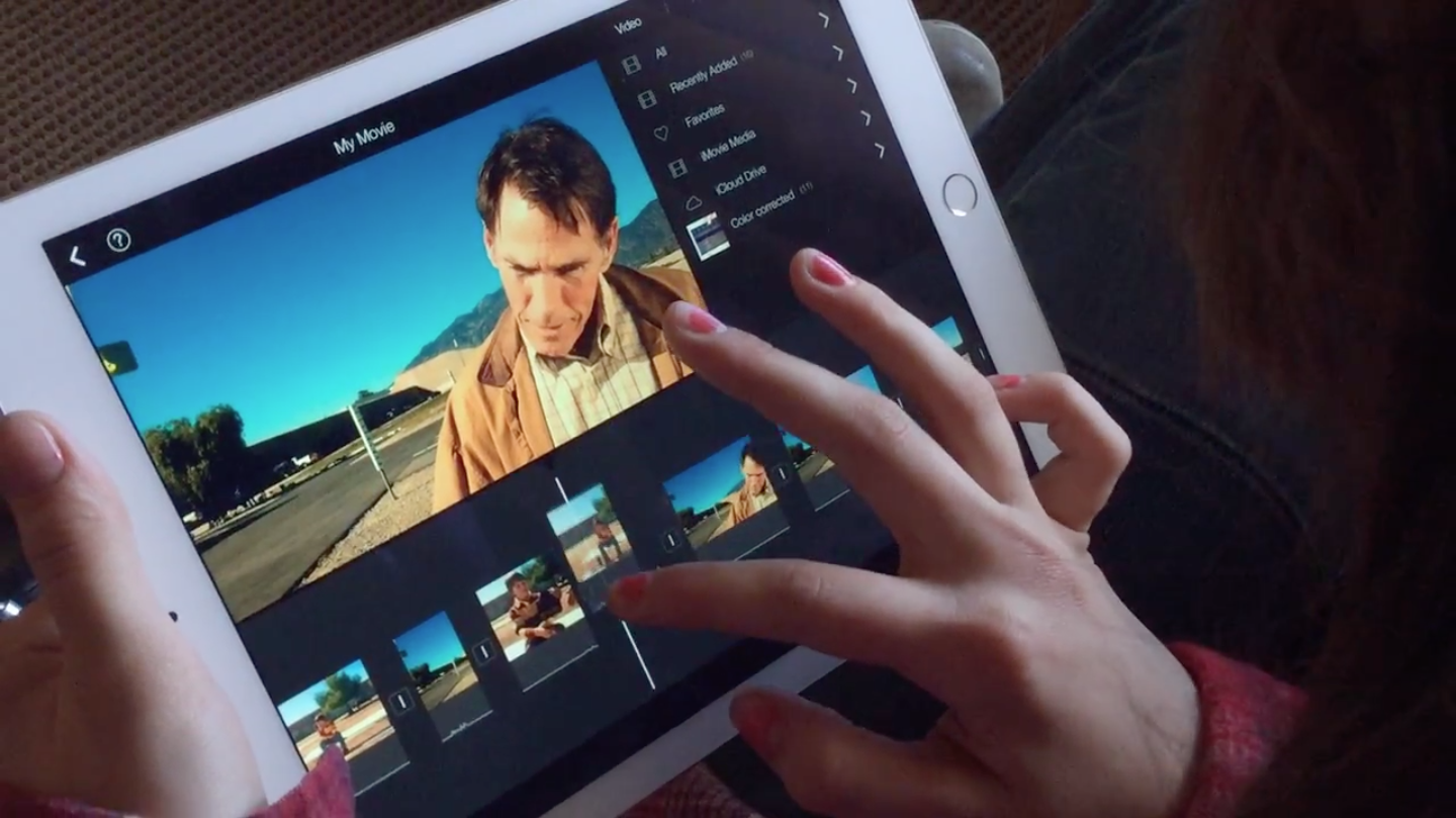
Everyone’s used iMovie, right? That’s a really shitty, horrible, mess of a non-linear editor. More popular versions are Final Cut, Avid, and Premiere. NLE packages often include bells and whistles to do certain quick compositing tasks, but they should not really be considered compositing tools. Their primary purpose is slip and slide shots around on timelines.
A shot is the smallest building block of your edit. It’s the set of frames between one cut and the next.
A bunch of related shots. How related they are is up to the editor and director, but typically it’s stuff that’s in the same location, at the same time.
This is different from compositing, this refers to how things are arranged in screen space. Where the character’s are in relation to the camera, the effect of a specific kind of lens used, and how things move through the frame. The impact of composition is obvious when many shots are cut together because the brain stores information about what was just on screen. This can be used to create a comfortable conversation on screen, or a slasher flick.
Typically the first shot in a movie, or a change of location, that establishes where things are. We see the Death Star, and TIE fighters whizz by to establish that we’re going to be spending some time with the Death Star.
A shot that is very similar to another. In visual effects, and animation, elements might be reused from scene to scene, like backgrounds, or lighting rigs.
A wide-angle lens is used. This can show “more” but space can feel unnatural the wider and wider you go.
A shot from really far away, usually with a wide-angle lens, often an establishing shot.
Typically of a human subject, and it includes most of the human subject in the frame. This is useful for showing where characters are sitting or standing when they are talking to each other.
A view of the upper 3/4 of a person. Torso, arms.
Tight framing on the subject of the shot. Typically a human face, but it could be a close-up of a button, or trigger that is important to the events occurring in the scene.
All up in your grille.
Usually used for exciting cafe scenes. The camera is perched over the shoulder of one person in the conversation, and aimed at the the other person across from them. Typically this is paired with the reverse view of a camera over the other person’s shoulder.
A view of one character, intercut with the view of another character. We assume the two are talking to one another.
Wikipedia. The rule can be broken to purposefully achieve certain effects on the audience. That is not an excuse to ignore it because you’re an art student and you think ‘rules’ are dumb. YOLO.
This is a guideline for how far the camera should move when cutting on the same subject. It’s a little hard to conceptually understand, but if you don’t move the camera around, and just push in or out on your cut, you’ll wind up with something that distracts the audience (a jump cut).
Your iPhone has this built in. A grid of lines produced by dividing the width of the screen, and the height of the screen, by three. The eye typically focuses on elements resting on those lines, and particularly on elements resting on the intersection of those lines. However, this is a guide and should not be taken literally.
Tilting the camera so it isn’t aligned with the ground. This can give a fun-house effect. It should be used sparingly, to intentionally produce a jarring, or unsettling result. It’s from German Expressionist directors, Deutsch. Americans just call them ‘Dutch’ because: America.
How you get from one shot to another. This could be a cut, it could be dissolve, it could be fancy matted out objects overlapping in to the next shot.
A camera cut is when footage is ends, and new footage begins. There are many different kinds of cuts.
Almost exclusively used in horror films, this is basically removing a chunk of time from within a shot. The camera appears to ‘jump’ from one position to the next. It is unsettling, hence the association with horror, and not 27 Dresses.
Cutting between two different shots, but the two shots have elements that graphically match between them. Prime example of this is 2001: A Space Odyssey when the femur is tossed in to the air and it cuts to the a nuclear weapons satellite in the exact same position in screen space. (One of my favorites is from The Fall, keep an eye out for the face and landscape in the trailer.)
In one shot, a character’s arm reaches forward, we cut, and the next shot we see a close-up of that hand grabbing an ice cream cone. Delicious, artisan-crafted, action-packed ice cream. The movement is continuous and impactful even though the cut occurred in the middle of it and the two shots could have been filmed at different times, and even with a stunt-hand. You mostly see this in action scenes, as characters flail around trying to land punches.
The speed of the cutting can affect the perceived passage of time. When camera cuts come fast and furious, things feel like they are happening very quickly. This is because your eyeballs are hit with new information in rapid succession. Action scenes, explosions, all that stuff that needs frenetic, chaotic energy. Use sparingly to achieve the desired effect, use excessively to look like Michael Bay.
You’ll never guess what this one is.
A shot that goes on for a really long time. That sounds pretty arbitrary, but it’s relative to the length of the other cuts in the film. If you have some big opening shot where you’re touring Serenity with a steadicam, then you have a long take. “Hey, look at me! I did something hard!” Is typically what the director wants the viewer to know by using this shot. Another, example that you either love or hate is the opening part of Gravity.
Going back and forth between one scene, and another. This can create tension by weaving together several events. The Battle of Endor at the end of Return of the Jedi is cross-cut between the Emperor’s throne room, the rebels on the surface, and the rebel fleet (there are smaller units to how that breaks down, but you get the point). The technique is used extensively in The Fifth Element often to comedic effect. Something is revealed to the audience by a character in one scene, as the character in another scene discovers the facts themselves.
One shot gradually turns in to another shot.
Have you seen a George Lucas movie? All those. Horizontal, diagonal, vertical, radial (shudder), everything where graphical element wipes the frame. More subtle examples are when an object, or person, in the scene moves past the camera and they are part of the wipe. You’ll see this in crowd scenes. Some headless bozo walks right to left in front of the lens and on the right, behind the bozo is the next shot.
A cheesy circle opens or closes to reveal the next shot. This is a kind of wipe.
We’re gonna need a montage.
Sometimes, a shot will only be a set number of frames, but it will have a few frames before and after the shot range just in case the editor, or director wants to ‘open up’ the shot and make a hair longer. Handles are not a requirement.
A software vendor, visual effects company, animation studio, or artist will stitch together some shots they feel are really good. About one to three minutes in length, it shows bits and pieces of the work either to submit for an award, or more commonly, to secure future work.
All the shots from the reel get a short explanation, usually in a spreadsheet. What software was used, what roles were involved, artist names, any potentially relevant information.